 |
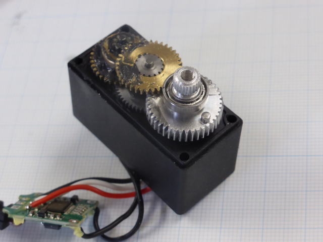
サーボのギヤー側の蓋を開けてみました。 金属製の立派なギヤーが見えます。 予想通り回転角制限ストッパー(アルミギヤに付いているピン)がありました。 I opened the lid on the gear side of the servo. You can see a splendid metal gear. As expected there was a rotation angle limit stopper (pin attached to aluminum gear). |
||||||
 |
蓋の方にはピンが当たる壁が付いています。 360度回転できるようにするにはピンを抜くか壁を削るかどちらかの処理が必要です。 The lid has a wall that hits the pin. In order to be able to rotate 360 degrees, it is necessary to either remove the pin or cut the wall. |
||||||
 |
ポテンショメーター(可変抵抗)も取れました。 当然普通のボリュームと同様に回転角が限られています。 230度くらいしか回りません。 抵抗値は10KΩでした。 ポテンショメーターとギヤーのストッパーを外せば単なるギヤードモーターになりそうです。 タミヤのギヤーボックスはいらなかったかも知れません。 I also got a potentiometer (variable resistance). Naturally the rotation angle is limited as with ordinary volume. I can only turn around 230 degrees. The resistance value was 10 KΩ. If you remove the potentiometer and the stopper of the gear, it seems to be a simple geared motor. You may not need a Tamiya gearbox. |
||||||
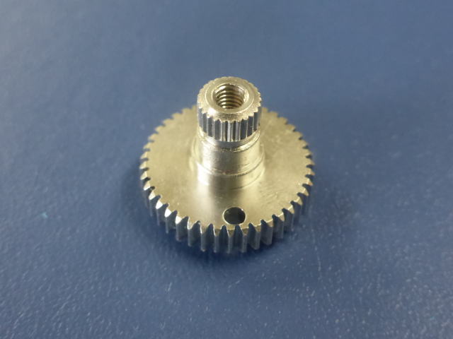 |
ギヤーに付いていたストッパーのピンを抜きました。 反対方向からM2のネジを当てて叩いたら簡単に抜けました。 蓋のストッパー用の壁を削る必要はなくなりました。 |
||||||
 |
基板上のポテンショメーターの端子に外部へ引き出すためのリード線を配線しました。 We wired a lead wire for pulling out to the potentiometer terminal on the board to the outside. |
||||||
 |
サーボモーターの蓋に穴を開けて外部ポテンショメーター用のリード線を引き出しました。 I drilled a hole in the lid of the servo motor and pulled the lead wire for the external potentiometer. |
||||||
 |
引き出したポテンショメーターのリード線を外部の可変抵抗に接続しました。 可変抵抗の極性が違っていると制御できません。 可変抵抗を回転フリーの状態にしてサーボを回転させて極性が正しくになるよう合わせました。 The lead wire of the pulled out potentiometer was connected to the external variable resistor. It can not be controlled if the polarity of the variable resistor is different. The variable resistance was rotated free and the servo was rotated so that the polarity became correct. |
||||||
| テストしました。 外部のポテンショメーターでフィードバックがかかって正常に動作しています。 見た目では前の動画と変わっていないように見えますがサーボ系の構成は異なっています。 外部のギヤーと外部のポテンショメーターがサーボ系を構成する要素として組み込まれたという事です。 つまり本装置全体がサーボモーターです。 たいへん良くできました。 I tested it. Feedback is applied with an external potentiometer and it operates normally. Although it seems that it does not look like the previous movie in appearance, the composition of the servo system is different. It means that the external gear and the external potentiometer are incorporated as elements constituting the servo system. In other words, the whole system is a servo motor. It was very good. |
|||||||
| 外部のギヤーと外部のポテンショメーターがサーボ系に含まれている事が分かる動画です。 サーボ動作中に手でレバーを動かすと自動的に戻ります。 手で動かしたのは制御系で言う外乱に当たり、外乱によって位置が設定値からずれると制御系はその位置のずれをゼロにするように動作します。 完璧ですね。 It is a movie that you can see that an external gear and an external potentiometer are included in the servo system. When you move the lever by hand during servo operation, it will automatically return. The thing moved by hand corresponds to the disturbance mentioned in the control system, and when the position deviates from the set value due to the disturbance, the control system operates so that the deviation of the position is zero. It is perfect. |
|||||||
 |
737用スロットルレバーの印刷データがThingiverseにあったので印刷して見ました。 リバースレバーを取り付けできる構造になっていました。 データには握りの部分も含まれていましたが印刷はされませんでした。 別にデータを作成してくっつけようと思います。 |
||||||
 |
2つのパーツを合わせた状態(右から見る) | ||||||
 |
2つのパーツを合わせた状態(左から見る) このようなパーツを使をうと本物っぽくなりますね。 |
||||||